For a project, documentation is not a “nice-to-have for later” but a working tool. It helps teams align on solutions faster, onboard new contributors more easily, and noticeably reduce troubleshooting time when something goes wrong in production.
In software development, especially in multi-team projects, effective cross-team communication is critical for project success. One tool that can significantly improve this communication is sequence diagrams.
In English, they are usually called sequence diagrams.
Why are sequence diagrams needed?
Sequence diagrams are visual representations of interactions between system components or actors over time. They help engineers see the order of method or function calls during execution of a specific workflow. This improves system understanding and helps detect potential issues or non-optimal flows.
Why is writing them as code more practical?
At first, I used to draw such diagrams in draw.io. Overall, it was quite time-consuming.
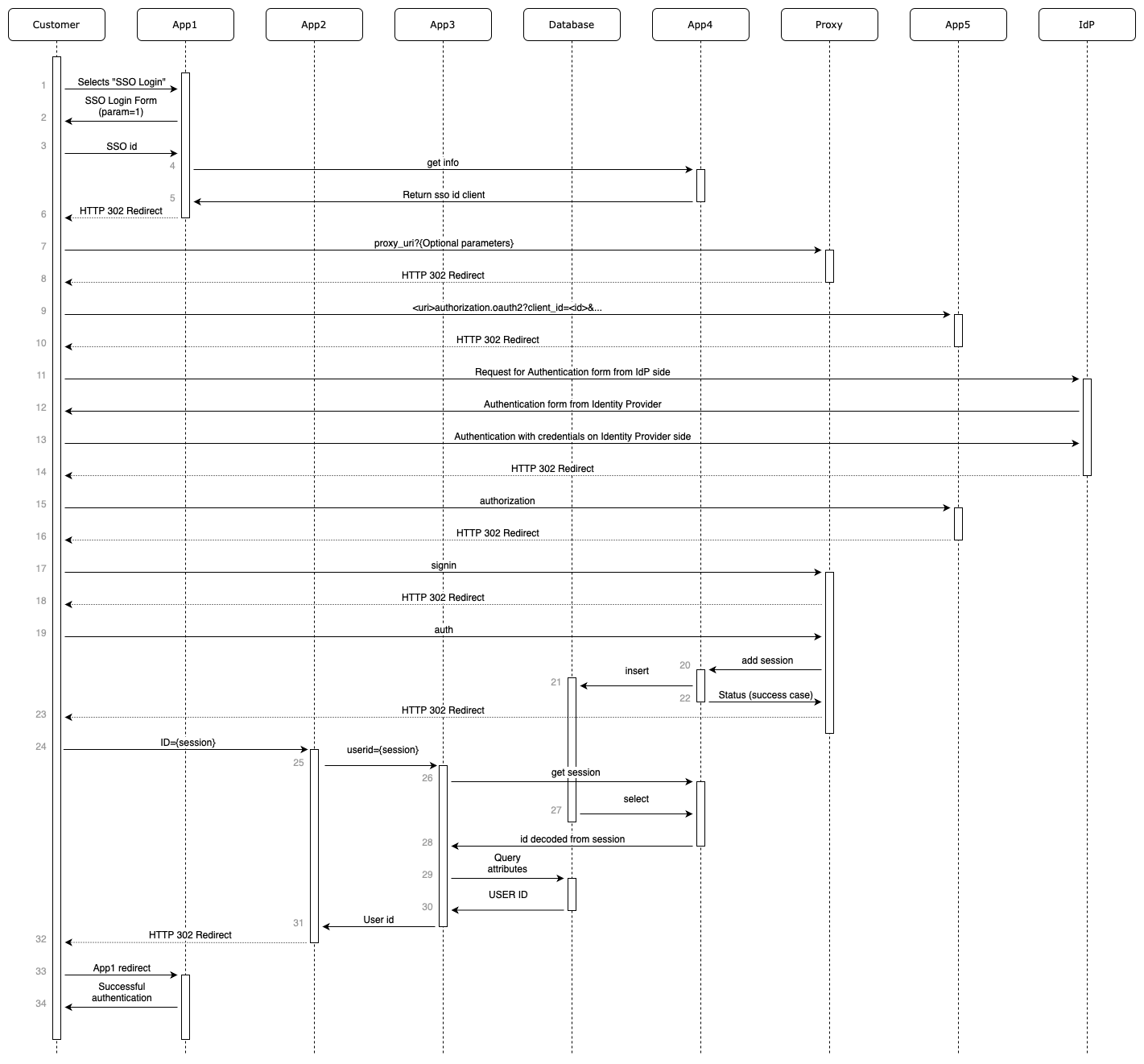
Download the diagram file above: sso-diagram.drawio.
Then I discovered PlantUML. Creating the first diagram in text was also labor-intensive, just like drawing in draw.io. But once I started making edits and producing similar diagrams, the advantages of code-based diagrams over image-based diagrams became obvious.
- Clarity and precision
- Using PlantUML to write sequence diagrams as code provides clear and precise interaction descriptions. PlantUML syntax is formalized and strict, reducing ambiguity and misinterpretation.
- Documentation integration
- PlantUML sequence diagrams are easy to embed into project documentation, such as Confluence. This gives all project participants convenient access to architecture and interaction visuals.
- Change versioning
- PlantUML makes it easy to track diagram changes and manage version history. This is especially useful in Confluence-based workflows, where you may need to restore previous versions quickly.
- Easy edits and follow-up diagrams
- Because PlantUML sequence diagrams are code, updates are fast and straightforward. Existing code can also be reused to build new diagrams, saving time and improving team efficiency.
A downside of coding diagrams is somewhat limited styling flexibility.
PlantUML
You can start coding/drawing a diagram directly in the browser:
https://www.plantuml.com/plantuml/uml/SyfFKj...
If diagram content is sensitive, you can run PlantUML locally with Docker. The same browser interface will then be available locally without internet access.
https://hub.docker.com/r/plantuml/plantuml-server
Request numbering
Diagrams serve two goals: first, to design and agree on technical solutions across teams; second, to troubleshoot running systems faster and route incidents to the right team.
For both cases, request numbering on the diagram helps a lot. When requests are numbered, teams can communicate in a concise format like: "request 11 sends these fields to your service, and response 12 returns unexpected data." This avoids long, confusing explanations.
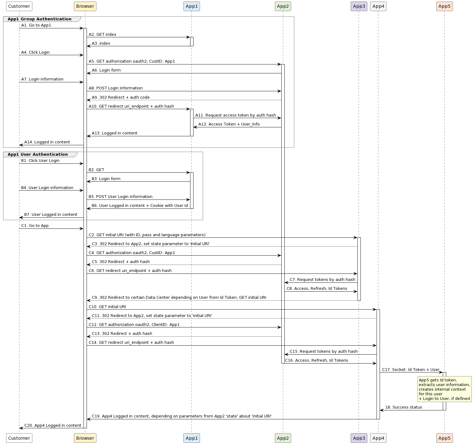
Single Sign-On diagram example
@startuml

<style>
group {
    LineThickness 1
    LineColor #4d4d4d
    LineStyle 1
  }

  groupHeader {
    LineThickness 1
    LineStyle 1
  }
</style>

skinparam sequence {
ArrowColor #000000
ActorBorderColor #000000
LifeLineBorderColor #000000
LifeLineBackgroundColor #FFFFFF
ParticipantBorderColor #000000
ParticipantBackgroundColor #FFFFFF
ParticipantFontColor #000000
BoxBorderColor #000000
BoxBackgroundColor #FFFFFF
BoxFontColor #000000 }

participant Customer order 10
participant Browser order 20 #fff2cc
participant App1 order 30 #dcebf7
participant App2 order 40 #e2efda
participant App3 order 50 #d9d2e9
participant App4 order 60 #F5F5F5
participant App5 order 70  #FCE4D6

group App1 Group Authentication

Customer -> Browser : A1. Go to App1
activate Browser
Browser -> App1 : A2. GET index
activate App1
App1 -> Browser : A3. index
deactivate App1

Customer -> Browser : A4. Click Login
Browser -> App2 : A5. GET authorization.oauth2, CustID: App1
activate App2

App2 -> Browser : A6. Login form

Customer -> Browser : A7. Login information

Browser -> App2 : A8. POST Login information
App2 --> Browser : A9. 302 Redirect + auth code

Browser -> App1 : A10. GET redirect uri_endpoint + auth hash
activate App1

App1 -> App2 : A11. Request access token by auth hash

App2 -> App1 : A12. Access Token + User_Info

App1 -> Browser : A13. Logged in content
deactivate App1

Browser -> Customer : A14. Logged in content

end

group  App1 User Authentication

Customer -> Browser : B1. Click User Login
Browser -> App1 : B2. GET
activate App1

App1 -> Browser : B3. Login form

Customer -> Browser : B4. User Login information

Browser -> App1 : B5. POST User Login information
App1 -> Browser : B6. User Logged in content + Cookie with User Id
deactivate App1

Browser -> Customer : B7. User Logged in content

end

Customer -> Browser : C1. Go to App

Browser -> App3 : C2. GET initial URI (with ID, pass and language parameters)
activate App3
App3 --> Browser : C3. 302 Redirect to App2, set state parameter to 'initial URI'

Browser -> App2 : C4. GET authorization.oauth2, CustID: App1

App2 --> Browser : C5. 302 Redirect + auth hash

Browser -> App3 : C6. GET redirect uri_endpoint + auth hash

App3 -> App2 : C7. Request tokens by auth hash

App2 -> App3 : C8. Access, Refresh, Id Tokens

App3 --> Browser : C9. 302 Redirect to certain Data Center depending on User from Id Token, GET initial URI
deactivate App3

Browser -> App4 : C10. GET initial URI
activate App4

App4 --> Browser : C11. 302 Redirect to App2, set state parameter to 'initial URI'
Browser -> App2 : C12. GET authorization.oauth2, ClientID: App1

App2 --> Browser : C13. 302 Redirect + auth hash

Browser -> App4 : C14. GET redirect uri_endpoint + auth hash


App4 -> App2 : C15. Request tokens by auth hash

App2 -> App4 : C16. Access, Refresh, Id Tokens
deactivate App2

App4 -> App5 : C17. Socket: Id Token + User
activate App5
rnote over App5
App5 gets Id token,
extracts user information,
creates internal context
for this user
+ Login to User, if defined
endrnote
App5 -> App4 : 18. Success status
deactivate App5

App4 -> Browser : C19. App4 Logged in content, depending on parameters from App2 'state' about 'initial URI'
deactivate App4
Browser -> Customer : C20. App4 Logged in content


deactivate Browser

@enduml
Link to the full version of this diagram on the PlantUML server: http://www.plantuml.com/plantuml/uml/fLLjRz....